What's going on in the video is a technique called photoelasticity, which is helpful for visualizing stress strain analysis for complicated geometry or loading conditions (or both!). Acrylic (and many other transparent materials) exhibit birefringence under stress, where the magnitude of the refractive indices throughout the material correspond to the magnitude of stresses at each point.
I hope to play with two items of MechE science with this EC - I can experiment with different constraint configurations by moving the dowels around, and I can observe the relative stresses on the dowels imposed by the load.
Exact constraint is the principle of only using as many constraints as there are available degrees of freedom. An object on a plane has three - two translations and one rotation - so the goal here is to achieve only three points of contact. Using exact constraint lets you avoid having your parts bind or behave in unpredictable ways.
My EC is the simplest version you could make - pins in holes. I wanted something configurable, so I set up a acrylic-lasercut grid of 5/16" holes to accommodate wooden dowels. The smaller holes on each side are for mounting the EC to a standard hacksaw frame.
 |
| Pins in holes |
The standard hacksaw makes a convenient experimental fixture for applying tension; I just have to attach my EC to the blade. The dullest hacksaw blade on the workbench got shortened (cannibalized with a hacksaw!) and two additional holes.
 |
| Saw blade taped onto table with VHB |
I borrowed a camera polarizing filter from a friend, and now we're ready for some science!
 |
| Spinning the polarizing filters makes patterns visible! |
I tensioned up the hacksaw and observed the birefringence patterns of just the grid plate. There are a few cool things here:
- You can immediately tell which screw got clamped down with a lock nut vs. the regular hex nut
- There are some nicks at the bottom of the acrylic plate that I didn't notice before
- You can see all the defects in the lasercut holes. Maybe there was some uneven melting?
- Since the regularly-spaced holes break up the neutral axis, you see some stress fields deflecting diagonally. At the same time, you get a cross-shaped pattern of dark spots between each hole which was not what I expected (I thought you'd get something more like magnetic-field-line-shapes)
 |
| Woah |
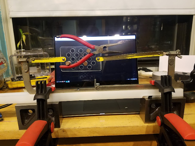
Back to the actual assignment - Exact constraint! Here it holds a pair of pliers with one pin on the bottom and two above, where it takes advantage of moment to hold things in place.
It supports this random item from my desk using two pins on the bottom and one constraining the side.
Cool birefringence patterns when I put force on the bottom two pins holding random-item-from-desk.
Also cool patterns happen when I exert a moment on the entire plate!


really excellent--was that your video using the computer screen as polaroiuzed light source? I would like to chare that
ReplyDeletealex
The video isn't mine, it's a random one from youtube: https://www.youtube.com/watch?v=3LNJmuYhA0s
ReplyDeleteThe gifs are using my computer screen as a light source though.