

 |
I started by waterjetting flat patterns from 0.5" 7075 MITERS stock,

originally from JACD and Battlebots 2015!
(they stuffed the plate in the back corner, for reasons I'll get to later)Why five?
Two are holiday presents, but the quality of a carabiner is dictated by how it performs under load. I will analyze the performance of these carabiners by doing experiments with the three sacrificial biners, and will also use them to figure out how these things get put together.
Below is one of the nice carabiners, currently getting engraved on the newly renovated MITERS CNC mill.

 |
| selected graphs from MakeItFrom.com |
My process for taking 7075-T0 to T6 went as follows:
- Heat to 900°F for 2 hours
- Immediately quench in water until room-temperature
- Heat at 250°F for 18 hours


I also didn't expect cracks to emerge. Half of the parts had cracks consistently 1/3 thickness from the surface, so I attribute this probably to some defect in the original plate. I attempted to fix this by removing more material from the smaller side when facing the parts (ending up with final thicknesses of 0.375".)


Let's talk a little bit about carabiner design.


I chose an offset-D shape (the most common) for my carabiner patterns. This blog has a good explanation of the different kinds of carabiner shapes. The key parameter for an offset-D is a basket (the bigger curve) around 3x as wide as the narrow curve. This shift transfers forces away from the weak gate and concentrates load on the stronger spine (the straight part.) In addition, the curvature radius on the two sides of the D should be identical and large enough to accept the rope you plan to use with it. All other dimensions were mostly eyeballing.
Another major choice was type of closure mechanism.
 |
| simply circus.com |
Fabrication of the nose and gate began with straight slots and pockets as rough approximations, then I refined the angles by filing down the edges until the gate smoothly fell into place.

Following carabiner construction, I had to figure out its spring mechanism.
Now this part was an absolute pain. I thought at this point I was on the home stretch, but ended up spending two additional days being frustrated at bent metal things.


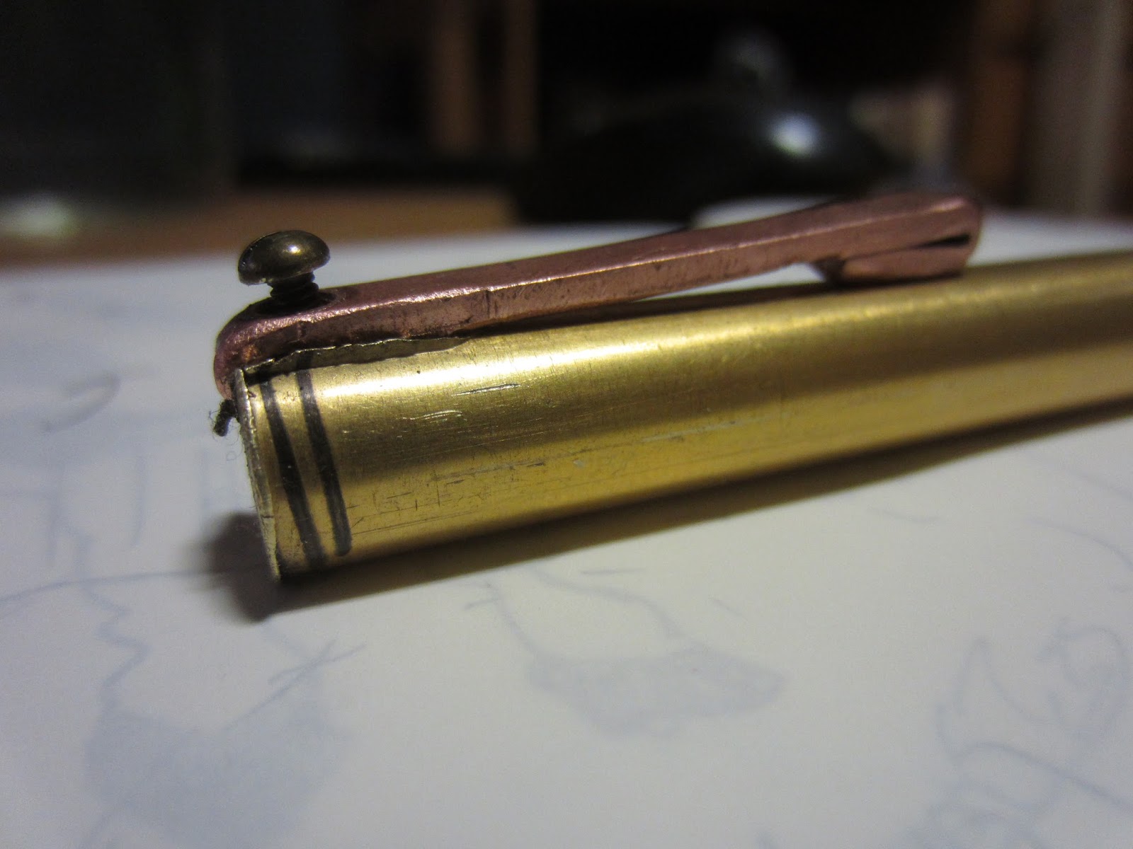
According to the patent drawing above, solid-gate carabiner hinges consist of a compression spring (#40) housed within the gate, actuated by an angled leaf spring (#101) lodged in a notch. The assembly is wedged within the gate when the hinge pin (#36) is in place. You can see the leaf spring in a real carabiner (upper right) peeking from the gate.
Finding a small compression spring was easy; finding a suitable leaf spring was not. After much trial and error, I discovered that constant-torque flat springs didn't work, and actual spring wire (balanced under a set screw) wasn't helpful. I eventually realized that the leaf spring didn't need to be springy at all; it simply needed to have the correct shape. Whacking and grinding small finish nails into shape successfully completed my artisanal hinge assembly.

Testing springiness of rough carabiner


Finally, I rounded off edges with files and passed paracord through to ensure no fraying ropes.
The gift carabiners were then complete!

Woo! Now for science.
The three remaining carabiners also had their load-bearing edges rounded off and received identical leaf-spring notches, though I did not insert springs into the gates. These got pull-tested until failure on an Instron tensile machine. The experimental setup, shown below, was conducted with a 20kn load cell at constant displacement (~2mm/min)

I'm not the first person to test carabiners here. I found a 2002 presentation where students tested fatigue in commercial 7075 carabiners. Their results showed that carabiners consistently broke on the spine near the upper basket, which makes a lot of sense.


It turns out I made a stupid mistake when designing my gates -- the gate's arms that grab onto the keynose were made too shallow and bent outwards at just 5kn, allowing the keynose to slip out.
Past 5kn, all my carabiners behaved as if the gates never existed, and failed at the standard 6-7kn for an open-gate 7075 biner.
On the bright side, having my carabiners fail at 6-7kn means that my amateur heat treatment actually worked! Woah.
 |
| carabiner slowly peeling apart |


all three carabiners broke their gates first (left) and a closeup of the damage (right)

The 2002 MIT experiment cycled commercial carabiners on a tensile machine for several iterations and monitored their load-displacement curve. They have an interesting change in slope when the gate catches against the nose, then another change in slope when the carabiner itself starts deforming.
My load-displacement curve is more disappointing, but follows the same pattern. There is a slight change in slope around the 1.5kn mark where the gate engages, then the slope levels out at plastic deformation. There are also distinct short spikes wherever the gate slips, followed by a final plummet at failure.
The third carabiner started out with a small crack near the hinge pin (I messed up while hammering the rivet) and therefore has a really weird graph. Oops.


Trial 1 (a&b):
The machine suddenly cut the experiment short, so the second attempt was with a likely compromised biner

Trial 2:
First downspike is the gate slipping; second is failure

Trial 3:
This gate failed early, probably due to prior cracks near the shear pin
 |
| Carabiners post-experiment from left to right (I couldn't find one of the pieces after the biner exploded) |
Notes for the future if I make any more of these:
- The keynose slot can afford to be shallower, so that the gate can be made thicker
- I should have made the gate pattern to be thicker than the carabiner pattern in the first place, instead of making them the same size.
- My derpy heat treatment method wasn't terrible!
- It still probably isn't quite on par with commercial 7075-T6
- Normally carabiners peel apart at failure, but mine exploded -- I probably didn't anneal it for long enough (250deg oven) and the metal was probably on the brittle side.
- The main fracture planes were, for the most part, right at the upper basket as expected.
- Making a keynose was not as difficult as I was originally led to believe.
- I should engrave things post-heat treatment, not before - removing the deformed bits while keeping the engravings intact was a pain.
I can expect the two gifted carabiners to hold up to 5kn loads and not fail until 6, making them more resilient than the waterbottle/backpack carabiners at the top of the post. They are definitely nowhere near the strength of true climbing carabiners!
Found a cool video of the manufacturing process for real carabiners!


