Jun 26, 2015

Brass Pen

Because I want to knurl something. And look at knurls.
Knurling = My current obsession.

First machining project of the summer is to create an everyday-use brass pen. 


I trade in some crufted steel rod for MITERS brass stock and start turning stuff to size. I went for a desired 3/8" diameter after finding a size that felt good in my hand. 

The ink cartridges I'm using were cannibalized from my favorite pens, Uni-ball's 0.38mm Signo pens. I adore these, so I opted to build the pen around these cartridges instead of using a more standard sizing. This involved a ton of caliper measurements and test fitting, but I enjoy that sort of thing.

After roughly sizing the brass, I bandsawed the rod in two and started shaping the front half. I started with a 20° taper but ended up going with something closer to 10°. I then rotated my tool to near-parallel and did a finish pass.


The knurling itself was glorious, but not quite as clean as the flashlight handle from 2.670. Knurls here serve several functions: grip surface, AESTHETICS, and hiding any differences in diameter between my front and back halves.

But 99% aesthetics.

I then face off the tip and drill a hole through the front, just large enough to admit the tip of the pen.  


Then, the pen gets flipped around (chuck grabs a collar of extra material on the back to avoid clamping on the knurls!) and a series of drills go through the back to match the rest of the ink cartridge dimensions.


And... I broke it. Time to go to bed; try again tomorrow :(

\
Take Two has slightly worse surface finish, but doesn't break the pen. After completing the front, I turn down the back to the same diameter.

My pieces mate with a 5/16"-18 thread. I discovered experimentally that cutting external threads with a die should always happen before drilling the interior cartridge hole. I know that's common sense, but I need to remind myself every so often when teaching other people to use machine tools.


I made a pen! And it writes!

I ended up needing a longer back-piece than I had originally anticipated, so part of my clamping-scrap ended up in the final pen. I hid the toolmarks with more knurls and some artistic tapers. In addition, the first thing I did with this pen was get a screw stuck in the barrel. The second thing I did with this pen was drill a hole through the back to poke the screw out.

that unfortunate screw hole
before/after comparison


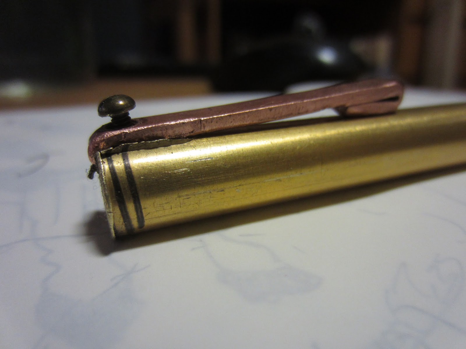
The third thing I did with this pen was send a picture to my mother, who reminded me that my grandfather loves shiny pens... so below is an in-progress photo of the next one!


Apr 20, 2015

CPW Swingset


Sandbox backhoes weren't the only building project happening during CPW. Jennie and I also decided to teach prefrosh how to build a swingset: we would cut the wood beforehand, and prefrosh would drill holes and attach pieces.

For a few prefrosh, this was their first time using a drill
We were originally going to stake down the base frames, but it turns out that the courtyard dirt is ridiculously packed for wooden stakes. We searched for metal stakes, but ended up building pontoon-style stabilizers instead. Since the ground was also slightly uneven, one frame still ended up rocking a bit if two people were on the swing at the same time.

Blueprint given to prefrosh. They rolled with it
The double 2x8 crossbeam turned out to be a good decision. Even though it was firmly seated on the A-frames by bolted supports and screwed directly to the 4x4 frame, the crossbeam still visibly twisted when two riders were out of sync. I doubt a thinner crossbeam would have sustained our abuse as well.

We had to replace our swing ropes every day since the wooden beams would fray the ropes and the ropes would wear grooves into the crossbeam, even with protective t-shirt padding. In the future we will replace the ropes with something like a webbing-light chain system that rubs less.

In the meantime, we enjoyed our functional swingset and the lovely weather of CPW.

CPW chairs being small children


Apr 19, 2015

Do you want to build a backhoe?

Welcome to CPW: Campus Preview Weekend, when we all pretend schoolwork doesn't exist and celebrate our prospective freshmen! The theme this year is "Kindergarten," which is a funny contrast to spring break's unofficial theme "Is College; No Parents"

I wanted to make a sandbox digger in the style of this instructable, out of dimensional lumber and prefrosh labor. The goal was to make a design on which prefrosh could learn how to use powertools (high error tolerance), but also have a fun, functional machine at the end of CPW.

Jennie and I sent in a design and safety proposal to our CPW chairs and to MIT's office of Environment, Health, and Safety. (EHS) Our proposed design looked like this:


EHS got back to us with various safety questions, and also requested extremely detailed drawings of our design and assembly process. I was going to make these anyway, since the plan was for prefrosh to do nearly all the construction (minus cutting wood). We sent in six pages of drawings in the style of LEGO blueprints.


Somewhere between making plans and starting construction, we decided to switch out bolts for 1/4" and 3/8" threaded rod, courtesy of MITERS.

Construction and assembly happened on the Saturday of CPW. Prefrosh learned the wonders of double-nut threading.

final product!
We discovered that 3/8" OSB (original plans called for 5/8") was not nearly structural enough to support our lazy susan turntable bearing, so we last-minute swapped them for 2x8 squares. We also ended up with creative supports for the 4x4 -> base connection.

But at the end of CPW, we had a working backhoe! Prefrosh built, Upperclassman tested.


Mar 2, 2015

Ripstik Assembly


The Ripstik was completed on the morning of February 2nd, just in time for XFair. A month later (3/2/15), I'm finally documenting the experience and realizing my delayed motors still haven't arrived!

Anyway, XFair was pretty fun. It took place in the midst of the Boston snowstorm, so I didn't even attempt to ride my deathtrap on the slick floorspace. Instead I took off the coverplates to show fair-goers how the internal mechanism worked.

photo cred: John Chow
There's still a lot of work left to do before the snows melt and before this will be rideable. My first (and only) trial run had me richocheting off walls in the MITERS hallway, for two main reasons. One, my torsion rod was too squishy to supply any meaningful force. If I placed a foot on one end of the board, I could step on and twist the other half with barely any resistance. That had to change.

Way back in freshman year, I found a slim bar extrusion of spring steel that could possibly substitute. It was too narrow to usefully put screws through, so I milled two clamps to house the bar.

original torsion bar

ripstik with new torsion bar installed


I also discovered during the trial ride that my ripstik was uncomfortably tall. Turns out when you learn how to ride on something an inch plus half shorter, anything else becomes weird. I removed the upper half of my caster assembly and merged its functions with the angle block, which took off 1/2". Maybe that will be good enough. 


Feb 10, 2015

Top Plate, Nutstrips, and Caster Parts


Ripstik: slowly and steadily coming together! 


The shiny blue shim steel I'm using for the top plates (aesthetic purposes) is really thin (0.03"), so it was sandwiched between sacrificial plywood and 1/8" 6061 aluminum to make sure it didn't warp while waterjetting, 


In addition to that, I'm milling angles on my tube cutouts so that they properly attach to the bent chassis.


The top plates will attach to the chassis with nutstrips, pieces of 0.5" square extrusion with 1/4-20 tapped holes every inch. Marking and powertapping all these holes took a while.


 Here I'm testing a quick caster-lock idea. A caster consists of an upper half and a lower half, with a common pivot shaft (1). If I have a slab that can slide through slots in both halves, I can lock and unlock the caster.

Once convinced that my lock idea would pan out, I proceeded to make all the parts.
Milling the angle blocks to 21.5°. These blocks connect the caster assemblies to the chassis.
kingpin/bearing assembly

freshly-waterjetted caster parts


Feb 3, 2015

TIG Welding Aluminum (poop welds)


I needed to fix cracks in my ripstik chassis caused by the bending brake. The front portion, in particular, really needed fixing. A well-intentioned friend found it cooling down in the oven, decided I probably kept it in the oven for a reason, and left it in while baking cookies at 350°F. (This is close to the tempering temperature for 2024) My metal ended up heat-hardening and even after another stint in the oven still ended up with massive cracks.


Some panels even had full blown tears on the edges. I definitely didn't want to rest any weight on cracked panels, so I asked the Media Lab shop guys for advice. They pointed me to the TIG welder, taught me how it works, and told me to practice on scrap.

It took me three days of practicing and a bunch of scrap metal before I felt ready to try the real thing. I've never welded before, so starting out on TIG and aluminum was especially difficult. Luckily for me I had plenty of practice material.


Judging the distance I needed to keep between the torch and my workpiece was pretty hard. I crashed a few times, which meant I had to stop and regrind the tungsten shaft.

Oops.


Once I was confident with my abilities on the scrapped interior shells, I started fixing cracks on the real thing. The result was not pretty, but it was effective.


photo cred: Melody Liu

+ me at the welding table!